Ynhâldsopjefte
Yn dit artikel beskôgje wy de twadde generaasje FX-Series / QX (S51), produsearre fan 2008 oant 2017. Hjir fine jo lontkastdiagrammen fan Infiniti FX35 / FX50 (2008, 2009) , 2010, 2011, 2012, 2013), Infiniti QX70 (2013, 2014, 2015, 2016, 2017) , krije ynformaasje oer de lokaasje fan de lontpanels yn 'e auto, en lear oer de tawizing fan elke fuse (fuse) layout) en relais.
Fuse Layout Infiniti FX35, FX50 en QX70 2008-2017
Sigaraanstekker (outlet) fuses: #20 (Front Power Socket) en #22 ( Console & Rear Power Sockets) yn 'e fusebox fan it ynstrumintpaniel.
Ynhâldsopjefte
- Fusebox foar passazjiersromte
- Fusebox Lokaasje
- Fuse Box Diagram
- Motorromte Fuse Boxes
- Fuse Box Lokaasje
- Fuse Box #1 Diagram (IPDM E/R)
- Fusebox #2 Diagram
- Fusible Link Block
- Relay Box #1
- Relay Box #2 (as foarsjoen)
Fuse Box Passazjiersromte
Fuse Box Lokaasje
It fusepanel fan it ynstrumintpaniel (J/B) sit efter it deksel ûnder it dashboard. 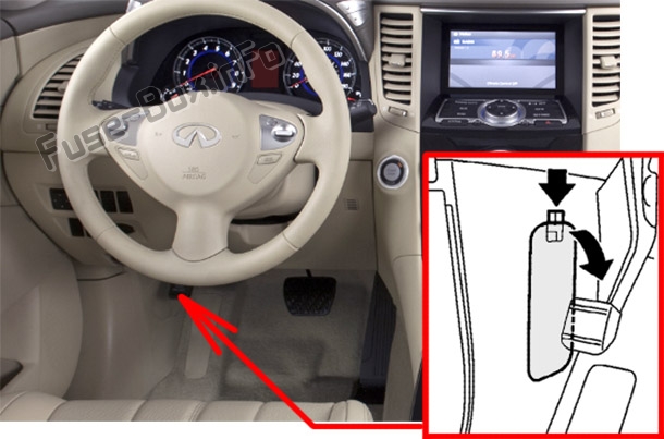
Fuse Box Diagram
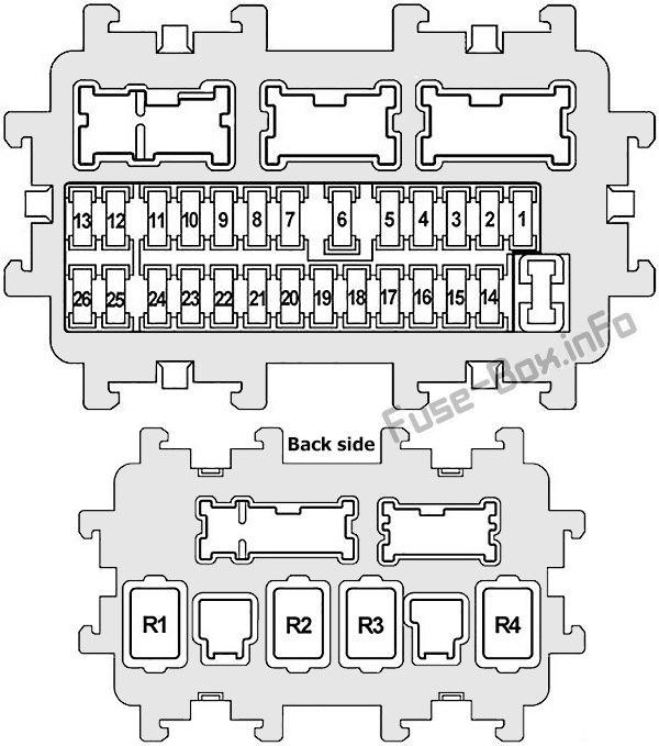
| № | Ampere Rating | Beskriuwing |
|---|---|---|
| 1 | - | Net brûkt |
| 2 | 10 | Contrôle-ienheid fan bewennersdeteksjesysteem, luchtkofferdiagnosesensorIenheid |
| 3 | 10 | Frontkombinaasjelampe, ionisator, klimaatregele sitrelais, unifoarme meter en A/C Amp., Lege bandendruk Warskôging Control Unit, Can Gateway, AV Control Unit, Exhaust Gas / Outside Odor Detecting Sensor, Auto Anti-dazzling Inside Mirror, ICC Brake Hold Relay, ASCD Brake Switch, Stop Lamp Switch, AFS Control Unit, Data Link Connector, Warning Systems Switch , Lane Departure Warning Buzzer, Lane Camera Unit, Compressor, Tel Adapter Unit, Heated Seat Relay, Heated Seat Switch (Driver Side/Passenger Side) |
| 4 | 10 | Kombinaasjemeter, Back-up Lamp Relay, Around View Monitor Control Unit, Sonar Control Unit |
| 5 | 15 of 20 | Accessoiresrelais |
| 6 | 10 | Key slot, klok, Data Link Connector, Rain Sensor, Intelligent Key Warning Buzzer, Auto Anti- Dazzling Inside Mirror |
| 7 | 10 | ICC Brake Hold Relay, Stop Lamp Switch, Body Control Module (BCM) |
| 8 | 20 | Bose Audio System |
| 9 | 10 | Key Slot, Push-Button Ignition Switch |
| 10 | 10 | Body Control Module (BCM), Automatic Drive Positioner Control Unit, Total Illumination Control Unit, Seat Memory Switch, Drive Seat Control Unit |
| 11 | 10 | Kombinaasjemeter, Unified Meter en A/C Amp., AWD Control Unit, CAN Gateway,Pre-Crash Seat Belt Control Unit (bestjoerderside / passazjierside) |
| 12 | - | Reserve |
| 13 | - | Reparate |
| 14 | - | Net brûkt |
| 15 | 10 | Doarspegels |
| 16 | 20 | Rear Windows Defogger |
| 17 | 20 | Rear Windows Defogger |
| 18 | 10 | E-SUS Control Unit |
| 19 | - | Net brûkt |
| 20 | 15 | Front Power Socket |
| 21 | 10 | Door Mirror Remote Control Switch, Unified Meter En A / C Amp., Multifunction Switch, Total Illumination Control Unit, AV Control Unit, Around View Monitor Control Unit, Tel Adapter Unit, Satellite Radio Tuner |
| 22 | 15 of 20 | Console Power Socket, Rear Power Socket |
| 23 | 15 | Blower Motor |
| 24 | 15 | Blaasmotor |
| 25 | - | Reparate |
| 26 | - | Reparate |
| R1 | Ignition Relay | |
| R2 | Rear Windows Defogger Relay | |
| R3 | 25> | Accessoire Relay |
| R4 | Blower Relay |
Motorromte Fuse Boxes
Fuse Box Lokaasje
Twa fuse blokken lizze njonken de batterij ûnder it deksel oan 'e passazjierskant. Om tagong ta guonitems, Jo moatte fuortsmite guon dielen fan 'e behuizing tichtby de batterij. De wichtichste fuses (Fusible Link Block) sitte op de positive terminal fan de batterij. 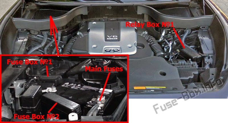
Fuse Box #1 Diagram (IPDM E/R)
| № | Ampere Rating | Beskriuwing |
|---|---|---|
| 1 | 15 | Brânstofpomprelais, brânstofpompkontrôlemodule, brânstofnivosensorienheid, brânstofpomp, motorkontrôlemodule (ECM) |
| 2 | 10 | Koelventilatorrelais #2 |
| 3 | 10 | Transmission Control Module (TCM), Snow Mode Switch |
| 4 | 10 | Fuel Injectors, Engine Control Module (ECM), Body Control Module (BCM) , Total Illumination Control Unit |
| 5 | 10 | ICC Sensor Integrated Unit, Accelerator Pedal Actuator, ABS Actuator And Electric Unit (Control Unit), Steering Angle Sensor, Yaw Rate 1 Side G Sensor, AWD Control Unit, Power Steering Control Unit, RAS Control Unit, ICC Warning Chime, Brake Booster Control Unit |
| 6 | 15 | Heated Oxygen Sensor #2 (Bank 2/Bank 1), Air Fuel Ratio (A/F) Sensor #1 (Bank 1/Bank 2) |
| 7 | 10 | Kombinaasjeskeakel |
| 8 | 10 | Stuurslotrelais |
| 9 | 10 | A/C Relay, compressor |
| 10 | 15 | Engine Control Module (ECM),ECM Relay, Condensor, Intake Valve Timing Control Solenoid Valve, Exhaust Valve Timing Control Solenoid Valve, EVAP Canister Vent Control Valve, Ignition Coils, EVAP Canister Purge Volume Control Solenoid Valve, Mass Air Flow Sensors, VVEL Control Module |
| 11 | 15 | Gasregelmotorrelais, Engine Control Module (ECM) |
| 12 | 10 | Achterlamp |
| 13 | 10 | Achterkombinaasjelampe, kentekenlampe, gloveboxlampe, totale ferljochtingskontrôle Unit, Front Power Socket, ATT Shift Selector, AV Control Unit |
| 14 | 10 | Headlamp LH (High Beam) |
| 15 | 10 | Koplamp RH (High Beam) |
| 16 | 15 | Koplamp LH (Low Beam) |
| 17 | 15 | Koplamp RH (Low Beam) |
| 18 | 10 of 15 | Foarste mistlamprelais |
| 19 | - | Net Brûkt |
| 20 | 30 | Front Wiper Relay |
| R1 | Net brûkt | |
| R2 | Starter Control Relay |
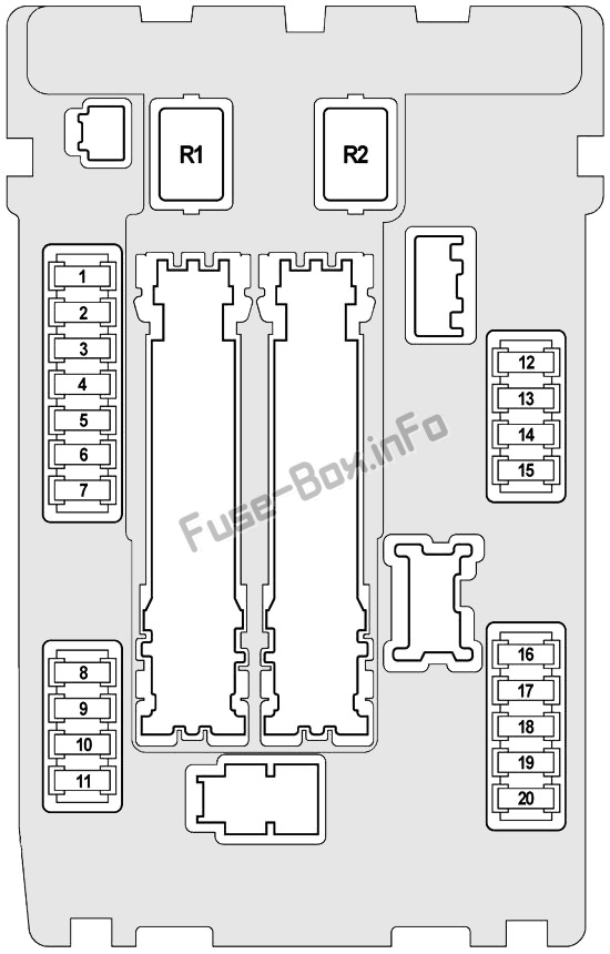
Fuse Kast #2 Diagram
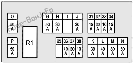
| № | Ampere Rating | Beskriuwing |
|---|---|---|
| 31 | 15 | Hoarnrelais №1, Alternator |
| 32 | 30 | Opsjeferbining |
| 33 | 10 | AWD-kontrôleUnit, Brake Booster Control Unit |
| 34 | 15 | Front Display Unit, AV Control Unit, Around View Monitor Control Unit, Woofer, Satellite Radio Tuner, Tel Adapter Unit |
| 35 | 15 | Back Door Control Unit |
| 36 | 10 | Transmission Control Module (TCM) |
| 37 | 20 | RAS-motorrelais |
| 38 | 10 | Hoarnrelay №2 |
| G | 50 | VVEL Actuator Motor Relay |
| H | 30 | Fuse Block J/B, IPDM E/R |
| I | - | Net brûkt |
| J | 30 | Pre-Crash Seat Riemkontrôleienheid (bestjoerderside) |
| K | 30 | Pre-Crash Seat Belt Control Unit (passazjierskant) |
| L | 40 | Body Control Module (BCM), Automatic Drive Positioner Cont, Driver Seat Control Unit, Lumbar Support Switch, Side Support Unit, Power Seat Switch |
| M | 30 | ABS-aktuator en elektroanyske ienheid |
| 50 | ABS-aktuator en elektroanyske ienheid | |
| O | 50 | Koelventilatorrelais №1 |
| P | 50 | Relaisblok №1 (Fuses: Q, 61, 62, 63) |
| R1 | Hoarnrelais №1 |
Fusible Link Block
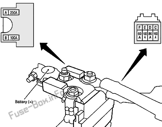
| № | Ampere Rating | Beskriuwing |
|---|---|---|
| A | 250 | Startmotor, dynamo,Sekeringen: C, D, E |
| B | 100 | Fuses: O (koelventilatorrelais 1), S (koelventilatorrelais 2) |
| C | 100 | Fuse and Fusible Link Block |
| D | 80 | IP Fuse Block (Fuses: 5, 6, 7, 8, 9, 10, 11), To Accessory Power Supply, to Ignition Power Supply |
| E | 100 | IPDM E/R (Fuses: 10, 11), To Ignition Power Supply |
| F | 60 | IPDM E/R (Fuse: 18 (Front Fog Lamp Relay); Headlamp High Relay, Headlight Low Relay, Tail Lamp Relay), To Ignition Power Supply |
Relay Box #1
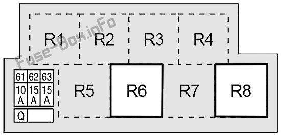
| № | Ampere Rating | Beskriuwing |
|---|---|---|
| 61 | 15 | Accelerator Pedal Actuator |
| 62 | 15 | Climate Controlled Seat Relay |
| 63 | 10 | Climate Controlled Seat Relay, Heated Seat Relay |
| Q | 30 | Automatyske efterdoarkontrôleienheid |
| R1 | Net brûkt | |
| R2 | <2 5> | Net brûkt |
| R3 | Net brûkt | |
| R4 | Net brûkt | |
| R5 | Net brûkt | |
| R6 | Hoarnrelais №2 | |
| R7 | Net brûkt | |
| R8 | ICC Brake Hold Relay |
Relay Box #2 (as foarsjoen)
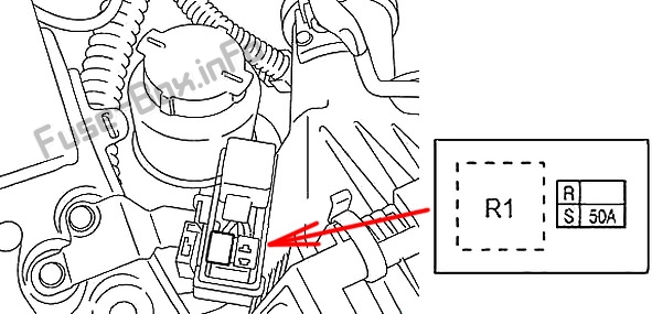
| № | AmpereWurdearring | Beskriuwing |
|---|---|---|
| R | - | Net brûkt |
| S | 50 | Koelventilatorrelais 2 |
| R1 | Koelventilatorrelais 2 |