Ynhâldsopjefte
Yn dit artikel beskôgje wy de tredde generaasje Nissan Quest (V42), produsearre fan 2004 oant 2009. Hjir fine jo lontkastdiagrammen fan Nissan Quest 2004, 2005, 2006, 2007, 2008 en 2009 , krije ynformaasje oer de lokaasje fan 'e lontpanels yn' e auto, en lear oer de tawizing fan elke fuse (fuse-yndieling) en estafette.
Fuse Layout Nissan Quest 2004-2009
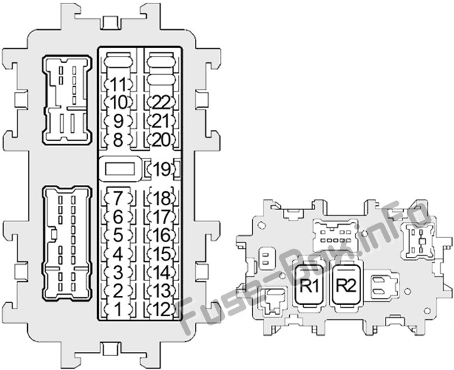
Sigaraansteker (outlet) fuses yn 'e Nissan Quest binne de fuses #5 (Front Power Socket 2, Rear Power Socket - 2nd Row) en #21 (Front Power Socket 1, Rear Power Socket - Cargo) yn it ynstrumint paniel fuse box.
Instrument Panel Fuse Box
Fuse box lokaasje
De lontkast sit efter it opslachromte links fan it stjoer. 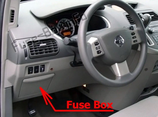
Fusebox diagram
| № | Amp | Beskriuwing |
|---|---|---|
| 1 | 10 | Pedaal oanpasse kontrôle ienheid, stopje Lamp Switch |
| 2 | 10 | Front Blower Motor Relay, Front Air Control |
| 3 | 15 | Body Control Module (BCM), Auto Anti-Dazzling Inside Mirror |
| 4 | 10 | Audio, AV Switch, Display Unit, Display Control Unit, Navi Control Unit, DVD Player, Satellite Radio Tuner, Body Control Module (BCM) |
| 5 | 15 | Front PowerSocket 2, Rear Power Socket (2e rige) |
| 6 | 10 | Door Mirror Remote Control Switch |
| 7 | - | Net brûkt |
| 8 | 10 | Doarspegel |
| 9 | 10 | Bestjoerderstoelkontrôleienheid, diode 1 |
| 10 | 15 | Achterblowermotor |
| 11 | 15 | Achterblowermotor |
| 12 | 10 | Automatic Speed Control Device (ASCD) Brake Switch, Data Link Connector, Combination Meter, Heated Seat Relay, Park Neutral Position Switch, Display Unit, Steering Angle Sensor, Display Control Unit , Navi Control Unit, Back Door Control Unit, Sliding Door Control Unit RH/LH, Sonar Control Unit, Daytime Running Lights, Hands Free Telephone |
| 13 | 10 | Airbag Diagnosis Sensor Unit, Bewenner Classification System Control Unit |
| 14 | 10 | Kombinaasjemeter, Park Neutral Position Switch, Automatysk dimmen binnen spegel |
| 15 | - | N ot Used |
| 16 | 10 | Injectors, Body Control Module (BCM), Engine Control Module (ECM) |
| 17 | 10 | Navi Control Unit, Back Door Control Unit, Sliding Door Control Unit RH/LH, Driver Seat Control Unit, Seat Memory Switch, Auto Drive Positioner Control Unit |
| 18 | 15 | Subwoofer |
| 19 | 15 | TransmissionControl Module (TCM), A/V Switch, Display Unit, Steering Angle Sensor, Combination Meter, Front Electronic Controlled Engine Mount, Display Control Unit, Key Switch, Front Air Control |
| 20 | 10 | Stoplamp Switch |
| 21 | 15 | Front Power Socket 1, Rear Power Socket (Cargo) |
| 22 | 15 | Brânstofdeksel iepener Relay, DVD Player |
| Relays | ||
| R1 | Blower | |
| R2 | Accessoires |
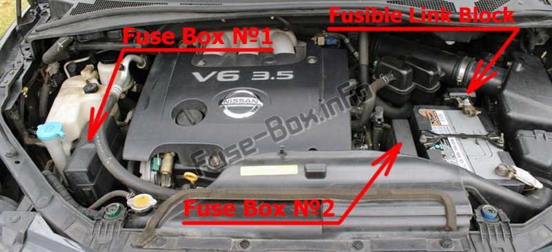
Fuseboxen yn it motorromte
Fusebox lokaasje
Sjoch ek: Jeep Compass (MK49; 2007-2010) fuses
Fusebox #1 diagram
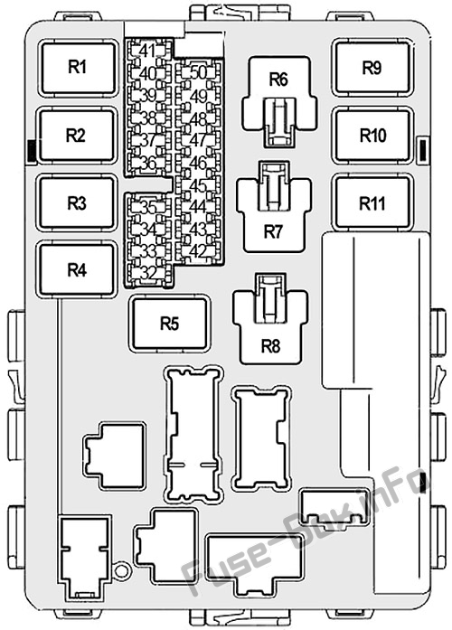
| № | Amp | Beskriuwing |
|---|---|---|
| 32 | 20 | Rear Window Defogger Relay |
| 33 | 10 | Air Conditioner Relay |
| 34 | 15 | IPDM E/R CPU |
| 35 | 15 | Engine Control Module (ECM), ECM Relay, NATS Antenne Amplifier |
| 36 | 15 | Headlamp Low ( rjochts), Diode 3 |
| 37 | 20 | Rear Window Defogger Relay |
| 38 | 10 | Koplamp Heech (links), Control Unit foar oerdeiljochten |
| 39 | 30 | Frontwisser Relais |
| 40 | 10 | Koplamp heech(rjochts), Daytime Running Lights Relay, Diode 3 |
| 41 | 15 | Tail Lamp Relay, Cornering Lamp Relay, IPDM E/R CPU |
| 42 | 10 | Heater Pump Relay |
| 43 | 15 | Relais foar mistlampe foar |
| 44 | 15 | Gasregelmotorrelais |
| 45 | 15 | Koplamp leech (links), oerdeisljochten |
| 46 | 15 | Luchtstreamsensor, kachelsoerstofsensor |
| 47 | 10 | Kombinaasjeskeakel (Frontwisser en Washer, Rear Wiper en Washer) |
| 48 | 10 | Transmission Control Module (TCM), Revolution Sensor, Turbine Revolution Sensor, A/T PV IGN Relay |
| 49 | 10 | ABS |
| 50 | 15 | Brânstofpomprelais |
| Relays | ||
| R1 | Motorkontrôlemodule | |
| R2 | Koplamp heech | |
| R3 | Koplamp amp Low | |
| R4 | Starter | |
| R5 | Ignition | |
| R6 | Koelventilator (No.1) | |
| R7 | Koelventilator (nr.3) | |
| R8 | Koelfan (nr.2) | |
| R9 | Gasregelmotor | |
| R10 | Brânstofpomp | |
| R11 | Foarkant mistLamp |
Fusebox #2 diagram

| № | Amp | Beskriuwing |
|---|---|---|
| 24 | 20 | Trailer Tow Power Supply |
| 25 | 15 | Hoarnrelais |
| 26 | 10 | Generator |
| 27 | 15 | Heated Seat Relay |
| 28 | 20 | Front Blower Motor Relay |
| 29 | 15 | Daytime Running Lights |
| 30 | 20 | Front Blower Motor Relay |
| 31 | 20 | Audio, BOSE Amplifier, Satellite Radio Tuner |
| F | 40 | ABS |
| G | 40 | Koelventilatorrelais 2 |
| H | 40 | Koelventilatorrelais 1, koeling Fan Relay 3 |
| I | 40 | Sircuit Breaker 1 (Slide Door Auto Closure System, Power Seat) |
| J | 50 | Body Control Module (BCM) |
| K | 40 | Ignition Switch |
| L | 40 | ABS |
| M | 40 | Circuit Breaker 2 (ferstelber pedaalsysteem, automatyske oandriuwingsposysje, automatyske slutingssysteem foar slide doar, elektryske sit) |
| Relays | ||
| R1 | Hoarn | |
| R2 | 22> | Frontblowermotor |
FerbineLink Block (Main Fuses)
It sit op 'e positive terminal fan' e batterij 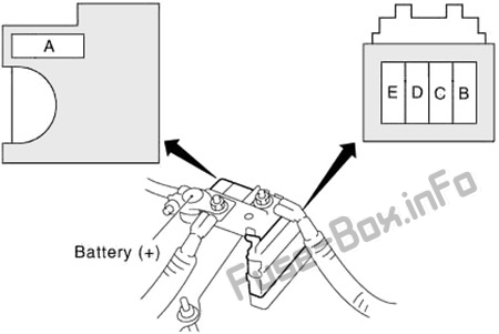
| № | Amp | Beskriuwing |
|---|---|---|
| A | 140 | Generator, zekeringen D, E |
| B | 80 | Accessoiresrelais (Fuses 4, 5, 6), Rear Blower Motor Relay (Fuses 10, 11), Fuses 3, 17, 18 , 19, 20, 21, 22 |
| C | 60 | Ignition Relay (Fuses 42, 46, 47, 48, 49, 50) , Fuses 33, 34, 35, 37 |
| D | 80 | Koplamp Heech Relay (Fuses 38, 40), Koplamp Low Relay (Fuses) 36, 45), zekeringen 32, 39, 41, 43, 44 |
| E | 100 | Fuses F, G, H, J, 24, 25, 26, 27 |
Foarige post Ford KA+ (2016-2017) fuses en relais
Folgjende post Ford Mustang Mach-E (2021-2022..) fuses